
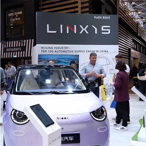
Data first: what the numbers reveal
Start with the figures: real-world driving data consistently shows a gap between laboratory efficiency numbers and on-street energy use. In some European fleets the delta can reach double-digit percentage points during cold starts and stop-and-go traffic — and Norway’s high EV adoption rates make it a useful living lab for these patterns. If you want to close that gap, the motor controller is a primary lever, because it mediates inverter switching, torque delivery, and regenerative braking behavior. Engineers and product teams need to talk to each other — and to specialists in automotive engineering — early, so the powertrain control strategy aligns with battery and vehicle architecture from the start.
How motor controllers shape on-road efficiency
Motor controllers do more than translate throttle input: they manage current, implement field-oriented control, and decide when to harvest energy back to the battery. Choices around PWM frequency, gate-driver design, and thermal management influence inverter losses and therefore range. A well-tuned controller reduces torque ripple and improves regenerative capture without compromising driveability. That technical nuance translates directly to user experience — smoother acceleration and fewer mid-trip range surprises — and it’s why controller firmware and hardware must be developed with system-level goals in mind.
From stress-tests to transit: where labs fall short
Laboratory stress-testing focuses on repeatable cycles and component limits: peak current pulses, thermal soak, standardized duty cycles. Those tests are necessary, of course, but they don’t always mimic urban microbursts — frequent accelerations, short bursts of high torque, and variable ambient temperatures. The result: a controller that looks great on a dyno but derates aggressively in real routes. A common oversight is assuming thermal profiles scale linearly — they often don’t, because packaging and automotive engineering decisions around cooling channels change the heat-shedding behavior. You’ll see similar mismatches when the vehicle’s car body design and undertray alter airflow — small changes, big effects.
Practical trade-offs and architectural alternatives
Design teams must weigh options: centralized inverter versus distributed in-wheel drives; silicon MOSFETs versus SiC devices; proprietary closed controllers versus open-source stacks. Centralized systems simplify cooling and wiring but can be heavier; in-wheel motors eliminate driveline losses at the cost of unsprung mass and packaging complexity. SiC inverters cut conduction losses and improve efficiency at high voltages, though they raise BOM cost and require careful EMC treatment. Each path shifts where you invest: hardware, thermal design, or software calibration — and the right mix depends on your target use case and cost structure.
Common mistakes teams make (and how to avoid them)
Teams repeatedly stumble over a few predictable issues:
- Over-relying on peak-efficiency numbers without testing realistic duty cycles — include urban WLTP or custom drive cycles early.
- Undermatching cooling capacity to expected continuous currents — always run worst-case thermal soak tests with full accessory load.
- Neglecting EMC and sensor noise when increasing switching speeds — it bites control-loop stability and torque precision.
Mitigations are straightforward: run hardware-in-the-loop (HIL) tests, validate controllers on target vehicles, and build iteration time for firmware updates into project timelines — that last bit saves weeks later.
Field checklist for engineers and product leads
Before you freeze a controller spec, confirm these points:
- Measured efficiency across representative duty cycles, not just peak torque points.
- Thermal derating maps tied to real packaging and ambient conditions.
- Regenerative braking strategy harmonized with braking system and user expectations.
- Clear EMI/EMC compliance plan and sensor-filtering architecture.
Run a pilot fleet in varied climates — urban, highway, and cold regions — to surface corner cases. —
Three golden rules for choosing your EV motor controller strategy
1) Prioritize system-level efficiency metrics, not isolated component specs. Measure delivered range and energy per kilometer under your expected duty cycle. 2) Insist on thermal and EMC validation with the final vehicle packaging — a controller that can’t breathe won’t meet field targets. 3) Build for updateability: choose controller hardware and firmware ecosystems that allow over-the-air calibration and incremental efficiency improvements without full hardware recalls.
These rules point toward resilient, scalable solutions that reduce time-to-market and long-term operating cost. For OEMs and fleet operators aiming to convert lab gains into street performance, collaborating closely with engineering partners and manufacturers that understand integration is the practical next step — and it’s precisely the kind of value companies like Wuling Motors bring to production programs.